Install an RM4210 or RM4250
Electrostatic Discharge (ESD) can damage electronic components. To prevent ESD damage when handling electronic equipment, always wear an anti-static wrist strap attached to an unpainted, grounded metal object. Ensure the wrist strap has maximum contact with bare skin. If an anti-static wrist strap is available, discharge static electricity from yourself and your clothing by touching a grounded metal object before handling electronic equipment.
The following section explains how to install the RM4210 or RM4250 onto the top of a coupon test station. For alternative mounting options, please contact Technical Services or refer to Optional Installations.
American Innovations recommends using AI part number 211061-000 (Belden 5308UE), or equivalent, for wiring inputs. To ensure a clean stable reading, keep field wiring as short as possible and use shielded twisted pair wire such as Alpha 2463C.
Complete the following steps to install the RM4210 or RM4250 on a coupon test station.
For the RM4210 or RM4250, you can attach either a PCR or a selectable current transducer attached to a PCR. Refer to Install Selectable Current Transducer for complete current transducer installation instructions before beginning the unit installation.
-
Remove the protective cover over the test station head.
-
Connect wiring harness individual wires to the respective test points on the test station.

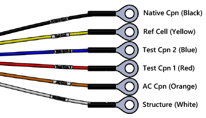
Wiring Harness Leads with Ring Terminals
The wires are color-coded and labeled for use with a Triton coupon test station. If connecting to another type of test station, note the following:
-
Do not connect the orange AC Cpn wire unless using a separate AC coupon.
-
The blue and red Test Cpn leads must be on the same connection.
-
-
For Triton coupon test stations only: disconnect the wire from the Switch.
-
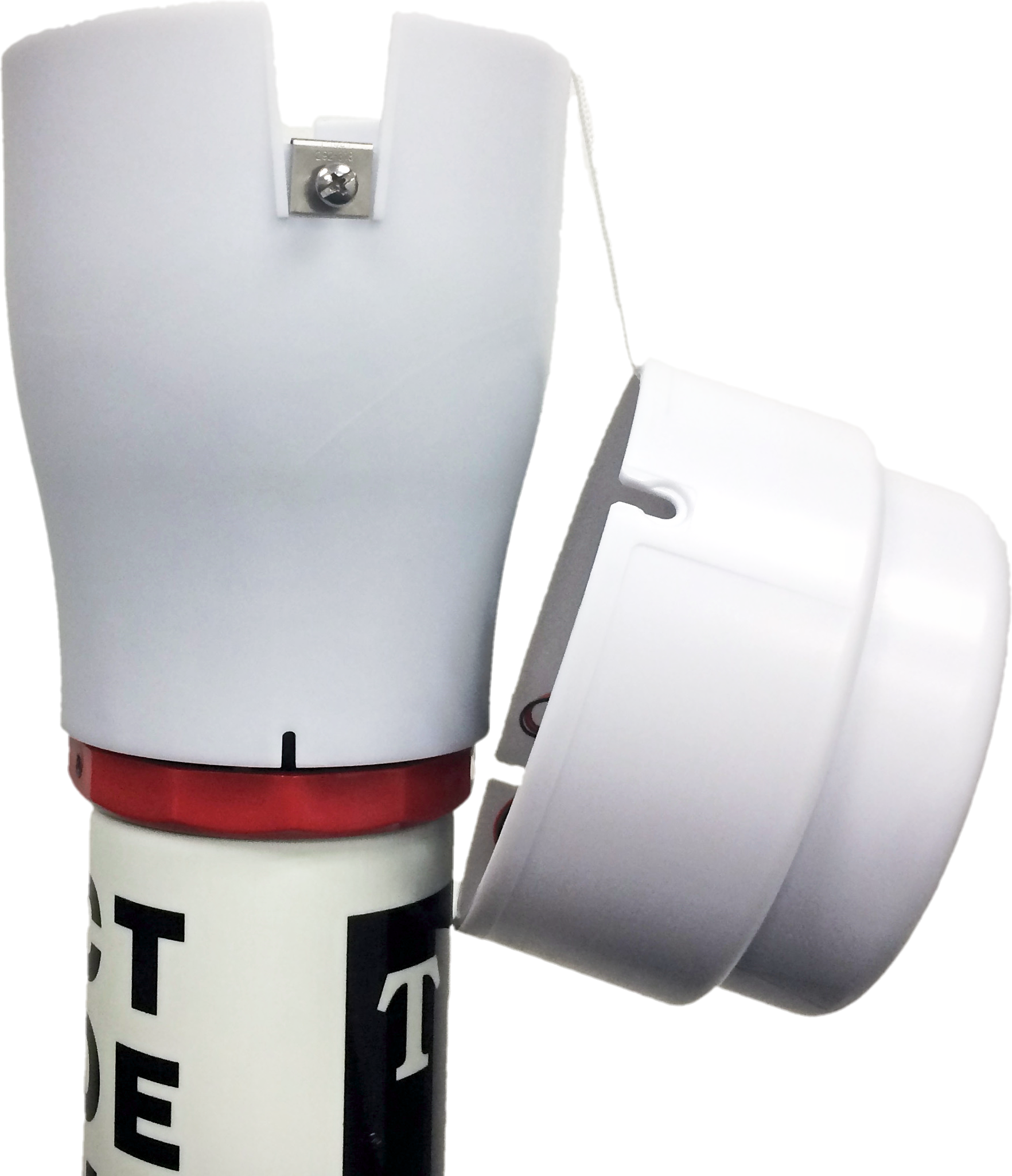
Slip the test station adapter over and onto the test station. Rotate clockwise to secure the adapter onto the test station.
-
Drop the tether cord attached to the RM4210 or RM4250 down into the test station. Ensure the tether end catches across the diameter of the test station. The tether will be used to support the unit if the test head needs to be accessed at a later time.

Test Station Adapter
-
Install the batteries into the bracket inside the unit. Secure with strap.

Battery Bracket and Battery Placement
-
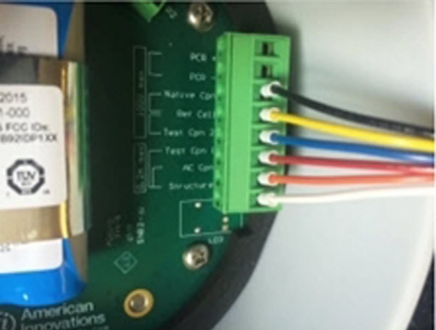
Connect the 8-pin terminal to the corresponding connection on the unit's board.

RM4210 8-pin Connector
-
OPTIONAL: connect a DC input or solar panel to the DC/Solar connector on the unit's board. Refer to Install and Connect Solar Panel or Install and Connect Power Supply for instructions.
-
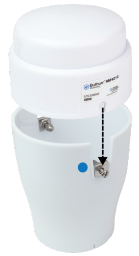
Place the unit onto the test station adapter, carefully wrapping the wiring harness inside the dome. Align the cut-out below the Bullhorn label on the dome to the screw (next to blue dot) on the adapter.

Adapter with Blue Sticker for Alignment with Unit Dome
-
Secure the unit by tightening the screws.
Do not twist the dome on the adapter if the cut-outs do not line up with the screws. Lift the dome off of the adapter and replace it in the correct position.
-
Test satellite reception for the RM4210 (refer to Test Satellite Reception).
-
Continue with Configuration Overview to configure the RM4210 or RM4250 for service.
If you are unsure of satellite coverage for the RM4210 or if the unit is placed in an area that is heavily covered by foliage, first check satellite reception by completing the steps in the Test Satellite Reception section. When finished, complete the installation procedures.