Connecting Devices to the RM3012
To ensure a clean, stable reading, keep field wiring as short as possible and use shielded twisted pair wire such as Alpha 2463C.
The RM3012 is connected to the oil sensor switch, annunciator, and a DC power source with the circular 9-pin cable assembly, which is shipped with the unit. The cable assembly is 20 feet long.
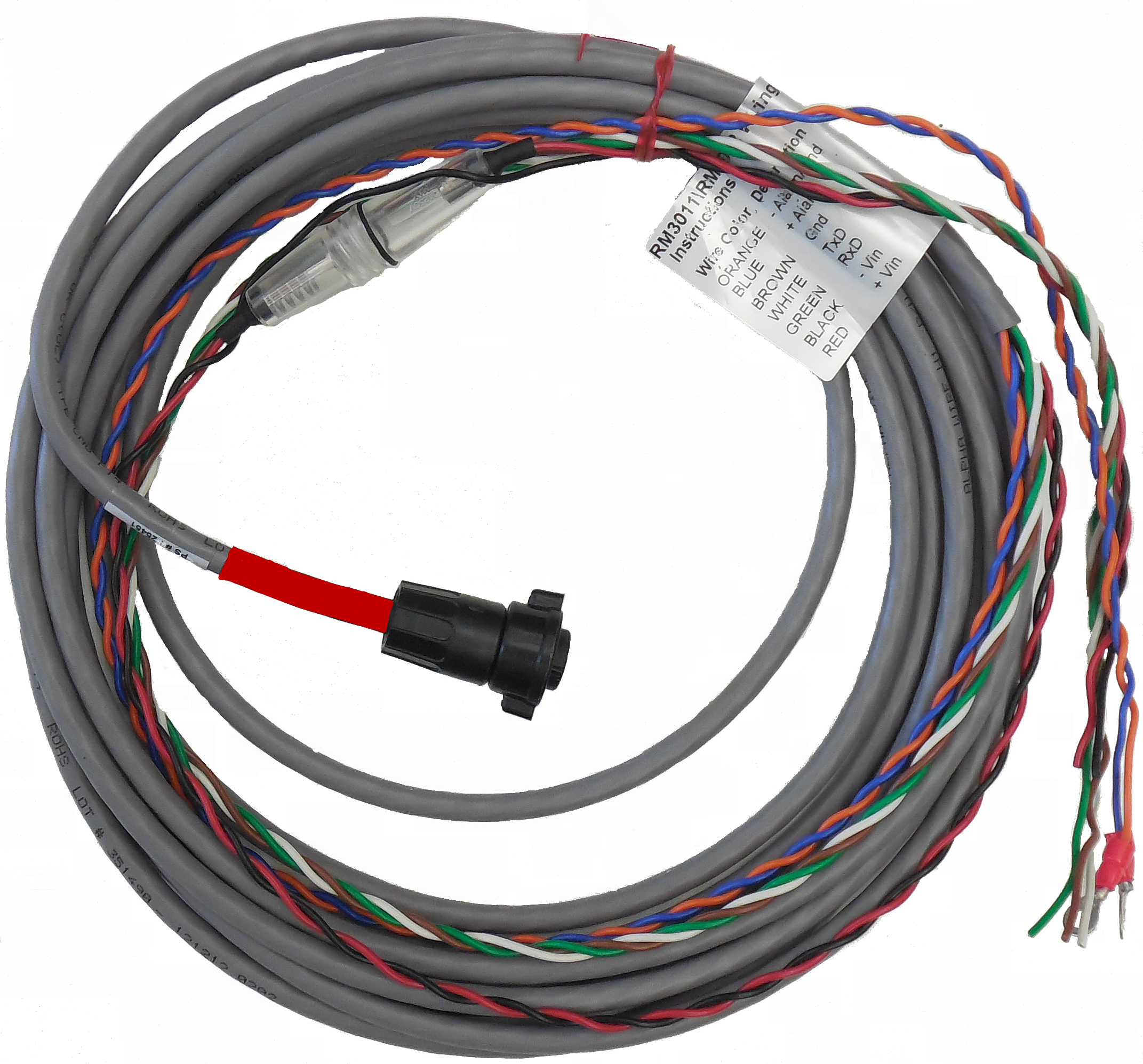
Circular 9-Pin Cable Assembly
The cable assembly is labeled with wiring descriptions to help with the installation of the oil sensor switch, annunciator, and DC power.
|
Front Panel Pin |
Wire Color |
Description |
|---|---|---|
|
3 |
Orange |
-Alarm/GND |
|
4 |
Blue |
+Alarm |
|
5 |
Brown |
Gnd (ground) |
|
1 |
White |
TxD |
|
2 |
Green |
RxD |
|
8 |
Black |
-Vin (voltage in) |
|
9 |
Red |
+Vin (voltage in) |
Complete the following steps to connect the devices to the RM3012:
-
Splice the compressor oil line into the compression tee. Secure the line by tightening the end compression fittings.
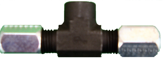
Compression Tee
-
Wrap Teflon tape around the oil sensor threads.
-
Attach the oil pressure sensor switch to the compression tee.
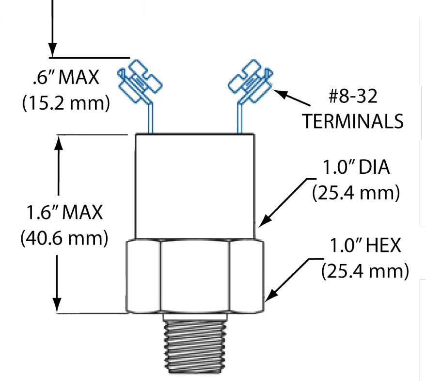
Oil Pressure Sensor Switch
-
If needed, connect spade lugs to the alarm wires (blue/orange) for connection to the oil pressure sensor switch terminals.
-
Connect alarm wires to the oil pressure sensor switch terminals.
-
If applicable, connect the receive/transmit/ground wires (white/green/brown) to annunciator.
-
For Altronic annunciators, connect the receive/transmit/ground wires to the screw terminals of the DB-9 adapter, using the following connections:
-
Connect green wire to wire terminal marked RXD (2).
-
Connect white wire to the screw terminal marked TXD (3).
-
Connect ground (brown) wire to the screw terminal marked GND (5).
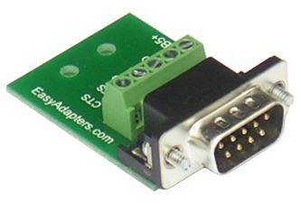
Annunciator DB-9 Adapter
-
-
Connect voltage wires (black = negative; red = positive) to DC source on compressor (requires 12-36Vdc input).
Connect the voltage wires from the 9-pin cable assembly to the non-switched side of the power strip of the compressor or to a continuous power source. A backup battery will provide temporary power to the RM3012 if the compressor or other power source shuts down.
-
Line up notch on the circular 9-pin connector to the 9-pin connector on the RM3012. Secure connector by tightening the wing nut ring until it clicks in place. The RM3012 powers on as soon as a connection is made with the connector pins.
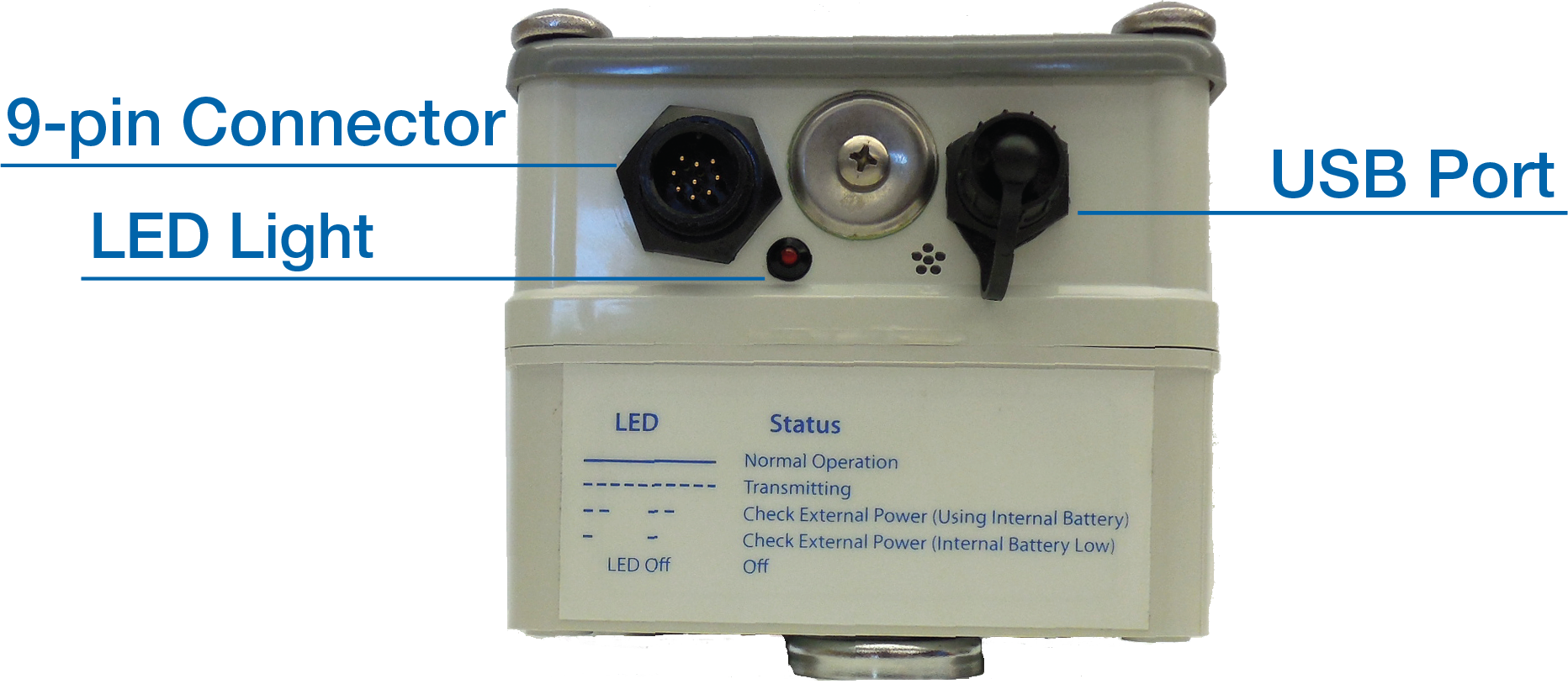
RM3012 Front Panel Features
The LED light located below the 9-pin connector will begin to flash on and off if you do not connect and power on an external DC power source to the RM3012. The RM3012 will use the internal battery, and the LED will continue to flash (except when transmitting when the light remains on), until a DC power source is supplied. Refer to Battery Replacement for instruction on how to replace the internal backup battery.