Mapping Registers for Modbus ASCII or RTU Input Device
Complete the following steps to map a register to a Modbus ASCII or RTU device:
-
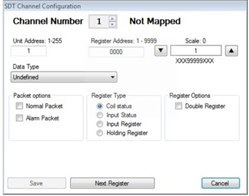
On the main configuration window, click the channel number you want to configure. For example, click Channel 1 to display a window similar to the example shown below.
You can also display a channel configuration window by clicking Tools > Settings > Channels. When the window displays, click Next Register to display the channel number you want to configure. If you are mapping a 12-digit register, make sure to select an odd-numbered channel on the main configuration window.
Modbus ASCII or RTU Configuration
-
Type the unit address assigned to the input device in the Unit Address text box. Valid entries are any number from 1 to 255. Entering zero (0) disables this feature.
-
Type the register address of the input device in the Register Address text box. Valid entries include any address from 1 to 9,999. Entering zero disables this feature.
-
Choose a scale value by clicking the up or down arrow buttons located next to the Scale text box. The up arrow moves the decimal to the left and the down arrow moves the decimal to the right.
The scale value you select displays below the text box. It shows an example of how the selected scale value applies to the register reading. The process the RM3011 uses to scale a raw register readings is as follows:
-
Divide the raw reading by the scale value.
-
Select the first six digits to the left of the decimal point for a 6-digit register or the first twelve digits to the left of the decimal point if working with a Double Register (12-digit register).
-
If necessary, add leading zeroes to the left of the number to produce either a 6-digit scaled reading or a 12-digit scaled reading if working with a Double Register.
If you are working with a 6 or 12-digit register and the scaled reading is larger than 6 or 12 digits respectively, the RM3011 reports a register reading of "999999". The Bullhorn website displays scaled readings according to the "multiplier" value you select on the website.
-
-
Click the arrow in the Data Type list box and select an option from the list that identifies the register data type.
If needed, refer to the technical specifications for the input device or contact the manufacturer to help determine the correct data type. An incorrect data type causes the RM3011 to report an incorrect register reading.
-
Choose either a Normal Packet or Alarm Packet from Packet Options.
-
Identify the Register Type by clicking the Coil Status, Input Status, Input Register, or Holding Register option button.
If needed, refer to the technical specifications for the input device or contact the manufacturer to help you determine the correct register type. An incorrect register type causes the RM3011 to report an incorrect register reading.
After choosing a register type, the UCT software modifies the register address by applying an offset value. The modified register address displays in the Register column of the Channels group box on the main configuration window. Offset values are automatically applied as follows:
-
Coil Status: zero (0) offset value
-
Input Status: 10,000 offset value
-
Input Register: 30,000 offset value
-
Holding Register: 40,000 offset value
-
-
If you are working with an odd-numbered channel and you want to map a 12-digit register, click the Double Register option box.
A check mark inside the check box indicates the channel is enabled. To disable the channel, clear the check mark by clicking the check box again.
-
Click Save + Next Register to save settings and display the next Channel Configuration window. If you do not want to configure another channel, click Save to save settings and close the configuration window.
