Installing the RM1250
Electrostatic Discharge (ESD) can damage electronic components. To prevent ESD damage when handling electronic equipment, always wear an anti-static wrist strap attached to an unpainted, grounded metal object. Ensure the wrist strap has maximum contact with bare skin. If an anti-static wrist strap is available, discharge static electricity from yourself and your clothing by touching a grounded metal object before handling electronic equipment.
The following section explains how to install the RM1250 with the flat base. For alternative installation options, refer to Other Installation Options or contact Technical Services.
To ensure a clean stable reading, keep field wiring as short as possible and use shielded twisted pair wire such as Alpha 2463C. American Innovations recommends using AI part number 211061-000 (Belden 5308UE), or equivalent, for wiring inputs.
Complete the following steps to install the RM1250:
-
Attach the flat base to a mounting bracket (either an existing bracket or the optional adjustable bracket).
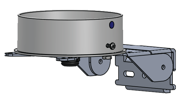
RM1250 Flat Base and Adjustable Mounting Bracket (optional)
-
If necessary, mount assembly to a structure, such as a pole, which is near the external device.
-
Bring the wires connecting the external device up through the bottom of the flat base.
-
Connect the external device to the 4-pin terminal.
-
Connect the 4-pin terminal to the corresponding connection on the RM1250.
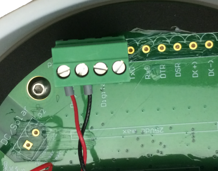
RM1250 4-pin Connector
-
Install the batteries into the bracket inside the RM1250. Secure with strap.
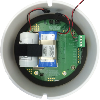
Battery Bracket and Battery Placement
-
Connect the two battery connectors to the battery connections on the RM1250 board.
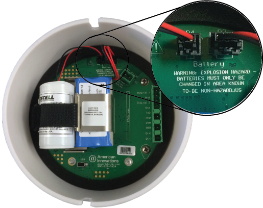
Battery Connections
-
Connect the larger, round battery to the P4 connection.
-
Connect the bundled pair of batteries to the P3 connection.
Once the batteries are connected to the unit, a Startup packet is sent to your Bullhorn Web account.
-
-
Place the RM1250 unit onto the base. Align the cut-out below the Bullhorn label on the dome to the screw (next to blue dot) on the base.
If you plan to configure the unit using a USB 5-pin mini-b cable instead of Bluetooth, do not place the unit on the flat base. Configure the unit first and then secure the unit on the base. Refer to RM1250 Configuration for configuration instructions.
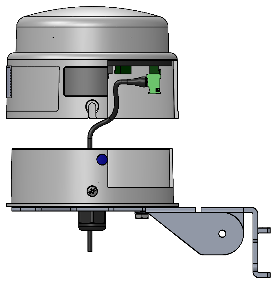
RM1250 Aligned to Base
-
Secure the unit by tightening the screws. Torque the dome screws and fitting to the following measurements:
-
dome screws - 10-12 in-lbs.
-
cord grip body - 60 in-lbs.
-
cord grip gland nut - 30 in-lbs.
Do not twist the dome on the base if the cut-outs do not line up with the screws. Lift the dome off of the adapter and replace it in the correct position.
-
-
Only if using AC power — turn rectifier ON to restore power to field wiring.