RM510C/RM510S Aux Data Settings
The RM510C/RM510S can capture auxiliary data including battery voltage, DC input voltage, interrupter state, interrupter verified, interrupter verified samples, and latitude and longitude. The Aux Data pane allows these readings to be configured. Readings can be disabled or enabled by clicking the checkbox next to each one.
To access the AUX data settings, click ![]() AUX Data in the Unit Setup navigation pane on the Unit Admin page.
AUX Data in the Unit Setup navigation pane on the Unit Admin page.
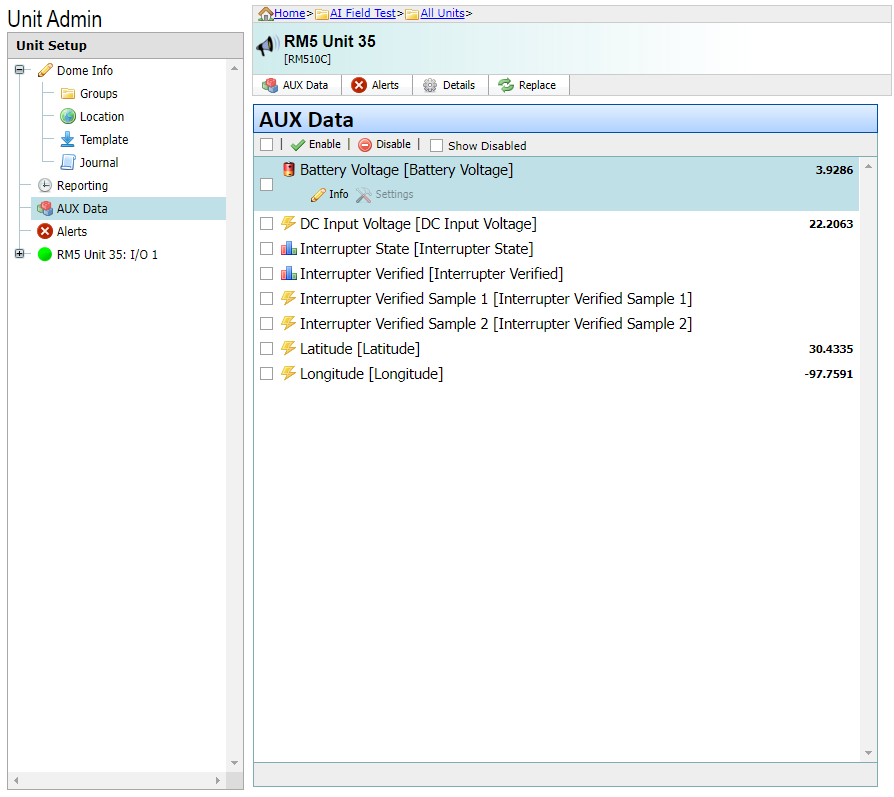
Aux Data Screen
To view or change the Aux Data fields, select a reading and then click on the Info icon.
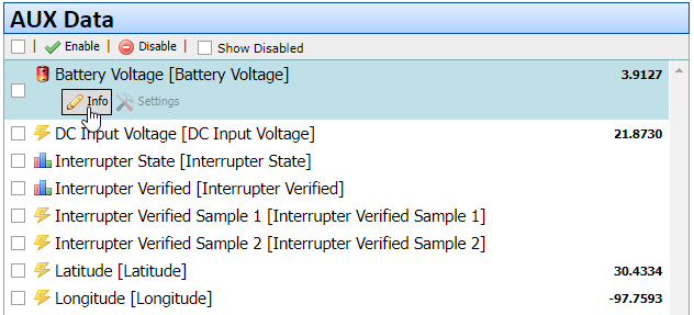
Aux Data Info
The following fields are available for Aux Data readings. Not all fields are available for all readings.
-
Alias — A user-friendly name for a unit data point. Enter a description that is meaningful to your company, such as a unique part number or other type of identifier.
-
Data Point Name — Name of the data point. This value is not editable.
-
Display As — Identifies the output of the data point. Options are As Is (Value as Decoded), Value Converted °C to °F, Value Converted °F to °C, or Descriptions for Values. Refer to Data Point Display As Options for more information.
-
Decimal Places — Identifies how many numbers appear after the decimal in a register reading.
-
Correction Factor — Applies to the POR data point (power on reset) or accumulator. The value is multiplied by the Correction Factor value. Correction Factor is a decimal number not equal to zero. Leave this field empty if you do not want to apply a Correction Factor.
-
Offset — Analog only. A decimal number added to the Data Point display value; shown in engineering units. Default is 0.
-
Engineering Unit Label — Identifies the unit of measurement. The Engineering Unit Label field includes a drop-down menu with pre-defined units. Users may also manually enter a custom value. Custom values must be less than 20 characters.
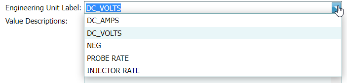
Engineering Units Drop-down Menu
-
Value Descriptions — For Analog data points only, displays code values and their description.
-
Add Description — For Analog data points only, identifies a code value and description. Enter a description of the code in the second field.
-
State Conversions — Identifies the state of the input. Also includes the option to identify the state with an icon. For inputs such as digital, normal reset, battery status, last packet medium, and switch over-current alarm (depending on unit type).

Digital Data Point Info - State Conversion